What Are CNC Turning Tools and How Do They Work?
Nov. 18, 2026
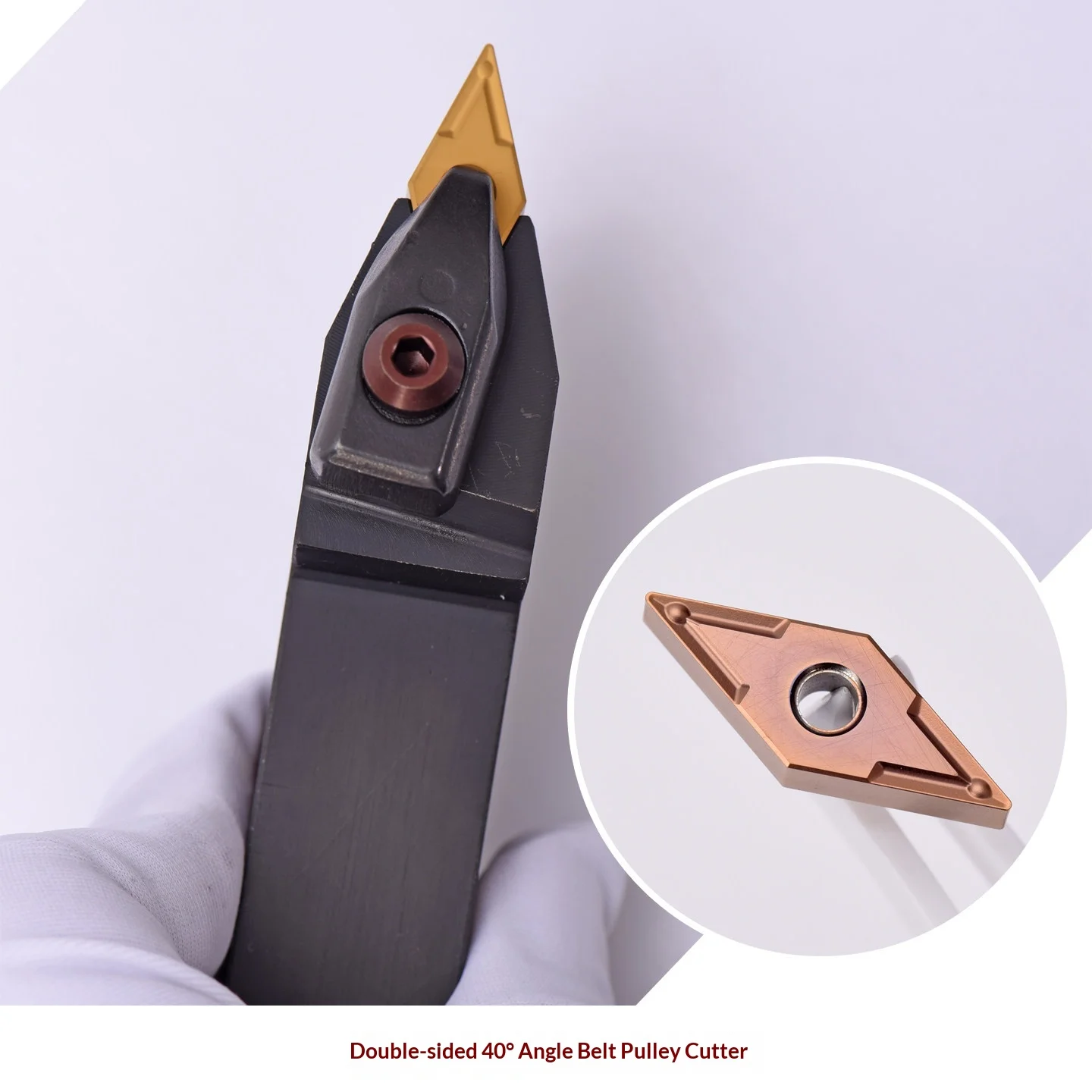
Cnc Turning Tools are cutting tools mounted in a CNC lathe or turning-center turret. The machine rotates the workpiece while programmed tool movements remove material to create diameters, faces, grooves, bores, threads, and other rotational features. The main categories include external turning tools, facing tools, boring bars, grooving tools, threading tools, drills, and parting tools.
When I explain CNC turning tools to machinists or beginners, I separate the complete tool assembly from the replaceable cutting edge. A working assembly normally includes the machine turret, tool holder, clamping system, insert or solid cutting tool, coolant delivery, and programmed cutting parameters. This distinction matters because a suitable insert can still produce poor results if the holder overhang, clamping force, tool height, or machine setup is incorrect.
!
What Are CNC Turning Tools and How Do They Work?
CNC turning tools are cutting tools used by CNC lathes to machine cylindrical, conical, threaded, bored, grooved, and faced features. Unlike milling tools, which usually rotate against a stationary workpiece, turning tools generally remain fixed in the turret while the spindle rotates the workpiece around its centerline. The CNC control coordinates spindle speed, feed movement, depth of cut, and tool position according to programmed instructions.
A CNC turning machine commonly uses two primary linear axes. The X-axis controls tool movement toward or away from the spindle centerline and determines the machined diameter, while the Z-axis moves the tool along the length of the workpiece. Some turning centers also include live tooling, a Y-axis, a C-axis, or sub-spindles for milling, cross-drilling, and multi-sided machining.
The cutting insert removes material through a controlled shear process. As the workpiece rotates, the cutting edge enters the material at a programmed feed rate and depth of cut, forming a chip that travels across the rake face of the tool. Tool geometry, workpiece material, cutting speed, coolant, and chipbreaker design determine whether the chip breaks into manageable pieces or forms long strands that can damage the part or machine.
What You Need Before Starting CNC Turning
Before selecting CNC lathe cutting tools, I collect the part drawing, material specification, stock diameter, required tolerances, surface-finish target, machine power, chuck or collet details, and expected production volume. I also confirm whether the operation is roughing, semi-finishing, finishing, threading, grooving, boring, drilling, or parting. Each operation places a different load on the cutting edge.
A basic preparation checklist includes:
- CNC lathe or turning center with a suitable turret position
- Correct tool holder and insert seat
- Insert grade matched to the workpiece material
- Workholding system with adequate gripping length
- Verified tool offset and tool-tip orientation
- Cutting-speed and feed-rate starting values
- Coolant or chip-control strategy
- Inspection equipment, such as calipers, micrometers, bore gauges, and surface-finish instruments
For small machine shops, I recommend recording the initial setup in a CNC turning tools checklist. The record should include insert code, nose radius, grade, cutting speed, feed per revolution, depth of cut, coolant condition, tool life, and measured part results. This creates a repeatable process instead of relying on memory or informal adjustments.
Step 1 — Prepare the CNC Turning Setup
What to Do
Begin by checking the machine condition and workholding. The chuck jaws, collet, soft jaws, or fixture must hold the workpiece with enough stiffness to resist cutting forces without deforming the material. Unsupported stock, excessive stick-out, and uneven gripping can cause vibration, taper, dimensional errors, and poor surface finish.
Mount the tool holder squarely in the turret and minimize overhang. For external turning, the insert should normally be positioned on the spindle centerline, while boring bars require careful alignment to prevent oversized or tapered holes. Confirm the insert is fully seated, the clamp or screw is undamaged, and the tool tip is free from chips before setting geometry and wear offsets.
Why This Matters
The cutting insert cannot compensate for an unstable setup. A long boring bar, thin-walled part, or poorly supported workpiece may produce chatter even when the insert grade and cutting speed are correct. In production, setup stiffness often determines whether the process can hold a drawing tolerance such as ±0.02 mm or whether repeated adjustment is required.
I also inspect turret alignment and spindle runout when dimensional results are inconsistent. Runout at the workholding system can create variation around the circumference, while turret misalignment can alter cutting depth and surface contact. These problems should be corrected mechanically before changing insert geometry.
Common Mistakes to Avoid
- Excessive tool overhang: Keep the unsupported length as short as the operation allows, especially with boring bars.
- Incorrect tool-center height: A tool positioned above or below center changes effective rake and clearance angles.
- Loose insert clamping: A loose insert can shift during cutting and create sudden dimensional errors or edge failure.
- Unverified offsets: Use a tool setter, touch-off routine, or measured test cut rather than entering an assumed offset.
Step 2 — Select the Correct Types of CNC Turning Tools
The major types of CNC turning tools correspond to the feature being produced. I usually select the tool according to the operation first, then choose the holder, insert shape, grade, nose radius, and chipbreaker. This approach avoids treating every insert as a general-purpose cutting edge.
| Operation | Typical Tool | Main Function | Common Example |
|---|---|---|---|
| External turning | Turning holder and insert | Reduces outside diameter | Shaft or pin machining |
| Facing | Facing tool | Produces a flat end face | Preparing stock length |
| Roughing | Heavy-duty turning tool | Removes large material volume | Forged steel blank |
| Finishing | Finishing holder and insert | Produces final size and finish | Bearing journal |
| Boring | Boring bar and insert | Enlarges or finishes an internal hole | Hydraulic cylinder bore |
| Grooving | Grooving holder and insert | Cuts narrow external or internal grooves | O-ring or retaining-ring groove |
| Threading | Threading holder and insert | Forms a controlled thread profile | Metric or unified thread |
| Drilling | Solid drill or indexable drill | Creates an initial hole | Center or through-hole |
| Parting | Parting blade and insert | Separates the finished component | Bar-stock cutoff |
External Turning and Facing Tools
External turning tools remove material from the outside diameter. Roughing tools generally use stronger cutting edges and larger depth-of-cut capability, while finishing tools use sharper geometries and smaller nose radii to reduce cutting force and improve dimensional control.
Facing tools move across the end of the workpiece to produce a flat surface. For a stable face, I check that the tool is correctly aligned with the spindle centerline and that the feed direction matches the holder orientation. A face that is not flat may indicate workholding error, tool deflection, insert wear, or incorrect machine geometry.
Boring Tools for Internal Machining
Boring tools enlarge existing holes and control internal diameter, concentricity, and bore surface finish. The main limitation is stiffness: a boring bar with a long length-to-diameter ratio is more likely to deflect or chatter. For small bore machining, I use the largest practical bar diameter, the shortest possible extension, and a cutting geometry suited to the material.
A boring assembly includes more than the insert. It may contain a steel or carbide bar, adjustable head, coolant passage, insert screw, and holder interface. KEUE CNC provides turning-related products such as small bore boring tools, CNC tool holders, adjustable holders, and turning inserts, which illustrates why buyers should evaluate the whole assembly rather than comparing insert prices alone.
Grooving, Threading, Drilling, and Parting Tools
Grooving tools use narrow inserts to create snap-ring grooves, oil passages, reliefs, and other recessed features. The insert width must match the drawing requirement, and the tool must be aligned accurately to avoid uneven groove walls. Chip evacuation becomes especially important in deep grooves because the confined cutting zone can pack with chips.
Threading tools use a controlled insert profile and synchronized feed. A metric thread with a 1.5 mm pitch, for example, requires the machine to advance the tool 1.5 mm per spindle revolution during the cutting pass. Parting tools require careful blade alignment, stable workholding, and controlled feed because the tool progressively loses cutting clearance as it approaches the centerline.
Step 3 — Understand CNC Turning Inserts and Tool Geometry
CNC turning inserts are replaceable cutting edges made from materials such as cemented carbide, coated carbide, cermet, ceramic, cubic boron nitride, or polycrystalline diamond. Coated carbide is widely used because it offers a balance between wear resistance, toughness, cutting speed, and cost across steel, stainless steel, cast iron, and non-ferrous alloys. Harder insert materials can support specialized applications but may be less tolerant of interrupted cuts or unstable setups.
Insert shape affects edge strength and accessibility. A round insert distributes cutting load across a large edge and is useful for profiling, but it requires more clearance and machine power. Square and diamond inserts provide different combinations of strength, approach angle, and access to shoulders, while triangular inserts offer multiple usable corners in a compact format.
The nose radius affects both finish and cutting force. A larger radius can improve theoretical surface finish and edge strength, but it also increases radial cutting force and may promote chatter on slender parts. A smaller radius reduces cutting force and reaches narrow profiles more easily, but it is more vulnerable to impact and excessive feed.
Tool geometry controls how the chip forms and how force enters the workpiece. Positive rake angles generally reduce cutting force and suit aluminum, thin walls, and lower-power machines, while stronger negative or neutral geometries can support heavier cuts in steel and cast iron. Clearance angle prevents the flank from rubbing against the machined surface, but excessive clearance weakens the cutting edge.
Chipbreakers should match feed and depth of cut rather than being selected by name alone. A finishing chipbreaker may work within a narrow feed range, while a roughing chipbreaker is designed for heavier chip loads. If the feed is below the chipbreaker’s effective range, the insert may produce long chips and rubbing instead of controlled chip breaking.
Step 4 — Match Material, Operation, and Cutting Conditions
How to Choose CNC Turning Tools
I use a five-part selection process: identify the material, define the operation, select the tool geometry, choose the insert grade and chipbreaker, then establish cutting conditions. This sequence connects the cutting edge to the actual machining problem. It also makes troubleshooting easier because each decision can be reviewed independently.
| Workpiece Material | Preferred Starting Direction | Geometry Consideration |
|---|---|---|
| Low-carbon steel | Coated carbide | Positive-to-neutral geometry with controlled chip breaking |
| Stainless steel | Tough coated carbide | Sharp edge with resistance to work hardening |
| Cast iron | Wear-resistant carbide or ceramic | Strong edge and efficient dust/chip management |
| Aluminum | Polished carbide or PCD | High rake, sharp edge, and large chip space |
| Titanium alloy | Tough carbide with heat control | Low radial force, moderate speed, and steady feed |
| Hardened steel | CBN or specialized carbide | Negative edge preparation and controlled engagement |
| Copper alloys | Sharp polished carbide | Prevent built-up edge and burr formation |
Cutting speed is normally specified in meters per minute or surface feet per minute, while feed is commonly expressed as millimeters per revolution or inches per revolution. Spindle speed can be calculated using the workpiece diameter and cutting speed, but the machine’s maximum spindle limit must also be observed. I treat manufacturer recommendations as starting values and validate them through chip shape, tool wear, power demand, dimensional stability, and surface finish.
Depth of cut should reflect the insert’s intended operation. A roughing insert may remove several millimeters per pass on a rigid machine, while finishing may use a radial depth below 0.5 mm depending on the material and required profile. If the finishing depth is too small for the insert geometry, the edge may rub instead of cut, causing heat, poor finish, and accelerated flank wear.
Step 5 — Run, Inspect, and Correct the Process
After loading the program, I use a single-block or reduced-rapid approach for the first cycle. I confirm the work offset, tool number, spindle direction, coolant command, approach position, and clearance path before allowing the tool to cut at full production speed. A dry run or graphics simulation can identify incorrect coordinate signs, unsafe retracts, and tool interference.
Inspection should cover the dimensions most affected by tool wear and deflection. For a turned shaft, I may check outside diameter, shoulder position, taper, roundness, and surface finish, while a bored component may require bore diameter, straightness, concentricity, and internal roughness checks. Statistical process control becomes useful when production volume is high because gradual drift can be detected before parts exceed tolerance.
Troubleshooting Common CNC Turning Problems
| Problem | Likely Cause | Corrective Action |
|---|---|---|
| Chatter marks | Excessive overhang, weak workholding, large nose radius, unsuitable speed | Shorten overhang, stiffen setup, reduce radial force, test speed adjustment |
| Poor surface finish | Worn insert, incorrect feed, rubbing, vibration | Replace or index insert, adjust feed, increase effective depth of cut |
| Burrs | Dull edge, incorrect tool direction, excessive feed | Use a sharper geometry, reduce feed, improve tool alignment |
| Long continuous chips | Wrong chipbreaker range, insufficient feed, poor coolant direction | Select matching chipbreaker, increase feed within limits, improve chip evacuation |
| Chip packing in grooves | Narrow chip path or inadequate coolant | Use a suitable grooving insert and direct coolant into the cutting zone |
| Dimensional drift | Flank wear, thermal growth, tool deflection | Add wear compensation, stabilize coolant, reduce cutting force, replace insert |
| Tapered bore | Boring-bar deflection or misalignment | Increase bar diameter, reduce overhang, verify center height |
| Premature edge failure | Interrupted cut, excessive impact, wrong grade | Use tougher grade, stronger edge preparation, or lower engagement shock |
CNC Turning Tools vs Milling Tools
The main difference between CNC turning and CNC milling is the source of relative motion. In turning, the workpiece usually rotates and the cutting tool follows a programmed path along the X and Z axes. In milling, the cutter rotates in the spindle and moves across a stationary or positioned workpiece using tools such as end mills, face mills, and drills.
Turning is generally efficient for rotational parts, including shafts, bushings, sleeves, threaded fittings, and flanges. Milling is better suited to pockets, slots, flat surfaces, keyways, and complex non-rotational profiles. A mill-turn center combines both methods, but the tool holders, spindle requirements, programming methods, and cutting conditions remain different for each operation.
Production Considerations: Accuracy, Finish, and Tool Life
The achievable tolerance and surface finish depend on the entire machining system, not the insert alone. Machine condition, thermal stability, spindle runout, workholding, tool stiffness, material consistency, programming, and inspection equipment all affect the result. For a precision component, I define the required tolerance and roughness before choosing the tool, rather than selecting a tool first and hoping the process will meet the drawing.
Tool life should be measured using a practical production limit. A tool may be considered worn when it causes dimensional drift, visible surface deterioration, excessive burrs, rising spindle load, or an unacceptable risk of edge failure. Tracking tool life by number of parts, cutting time, or material volume gives a clearer cost-per-part calculation than judging inserts only by purchase price.
KEUE CNC presents a product range covering turning inserts, grooving inserts, threading tools, small bore boring tools, tool holders, drilling products, and milling products. Its company information states that it was established in 2011 in Wenling, Taizhou, China, with a factory area of approximately 10,000 square meters, more than 100 exporting countries, and an independent research and development team. For custom tooling inquiries, the company indicates that coating, size, and precision can be customized, with quotation and delivery-time information commonly provided within 3–7 days after receiving product or workpiece details.
Conclusion
What Are CNC Turning Tools and How Do They Work? CNC turning tools are cutting tools mounted in a lathe turret while the machine rotates the workpiece and controls tool movement to remove material. Turning, facing, boring, grooving, threading, drilling, and parting tools each serve different feature and chip-control requirements.
I recommend choosing CNC turning tools through a documented sequence: identify the workpiece material, define the operation, select holder and insert geometry, match grade and chipbreaker, set cutting speed and feed, then verify the result through inspection. Pay particular attention to tool overhang, nose radius, rake angle, clearance angle, edge preparation, and machine stiffness because these factors directly affect accuracy, surface finish, productivity, and tool life. For a repeatable purchasing decision, compare the complete tool assembly—including holder, clamping method, insert, and turret interface—rather than comparing insert cost alone.