Small Bore Boring Tool Nose Radius: How to Choose the Right Size
Sep. 08, 2026
When I select a small bore boring tool nose radius, I start with the bore diameter, available radial depth of cut, boring-bar diameter, overhang, workpiece material, and required surface finish. The general rule is to choose the largest radius that fits the cut and remains stable, but a smaller radius is usually safer for long overhangs, thin walls, light finishing cuts, and chatter-prone bores.
What Is a Nose Radius on a Small Bore Boring Tool?
The nose radius is the rounded transition between the insert’s cutting edges. On a small bore boring bar, this radius directly affects cutting-force direction, chip thickness, theoretical surface roughness, edge strength, and the amount of clearance available inside the hole.
A larger radius spreads the cutting load across more edge length. That can improve insert strength and reduce theoretical roughness when the boring bar and workpiece are rigid enough. However, the same radius requires more radial engagement and can increase cutting forces, deflection, vibration, and the risk of rubbing during a light cut.
A smaller radius produces a sharper point that requires less radial depth of cut. It is often more suitable for small internal diameters, thin sections, interrupted stock, long tool overhangs, and finishing passes with limited remaining material. The trade-off is lower edge strength and a greater risk of chipping when feed rate, workholding, or tool alignment is unsuitable.
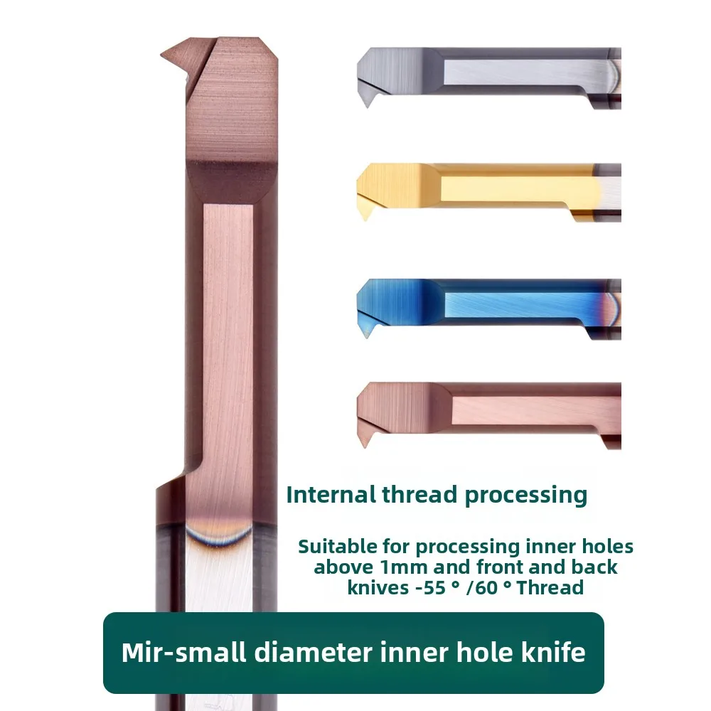
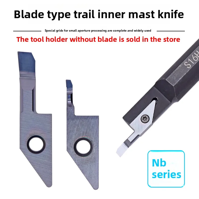
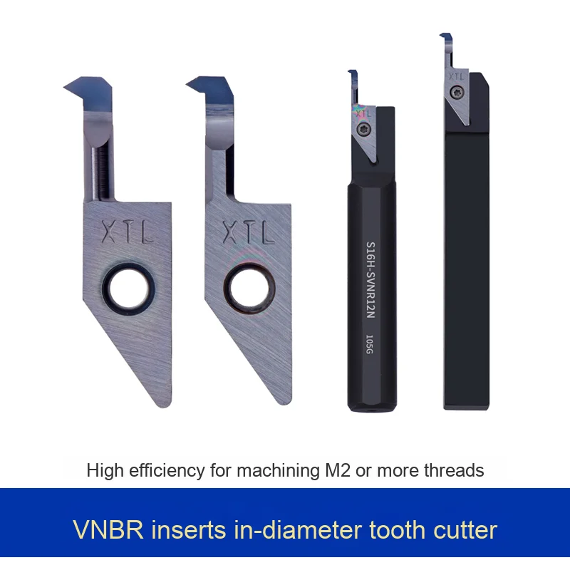
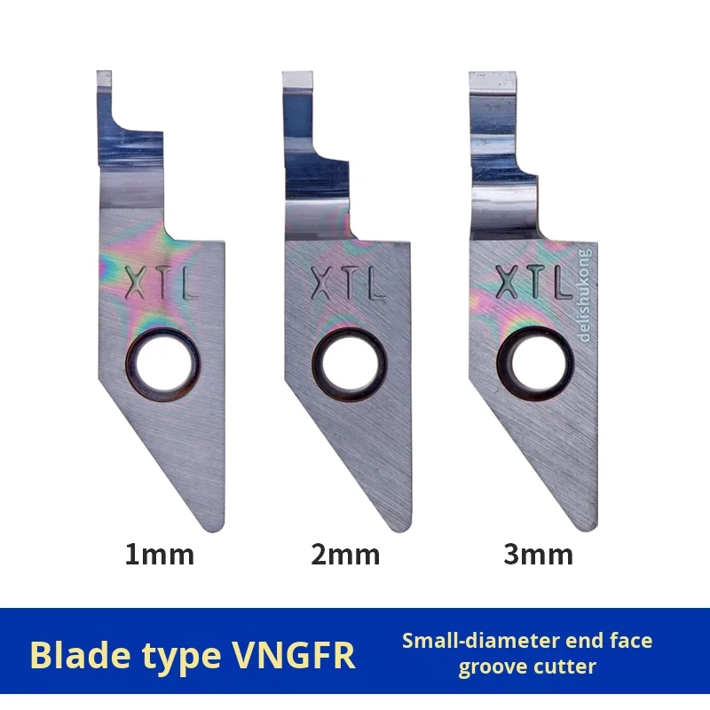
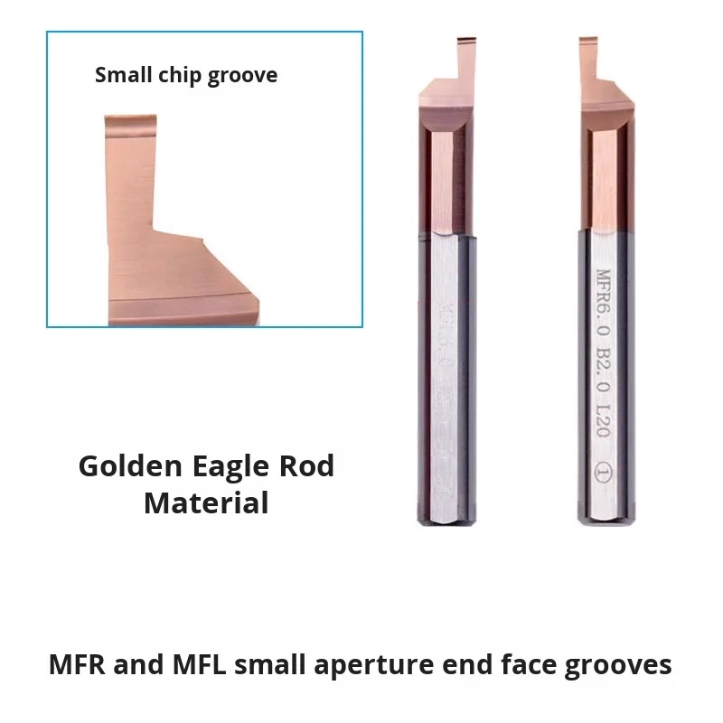
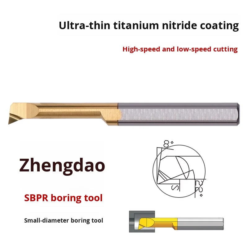
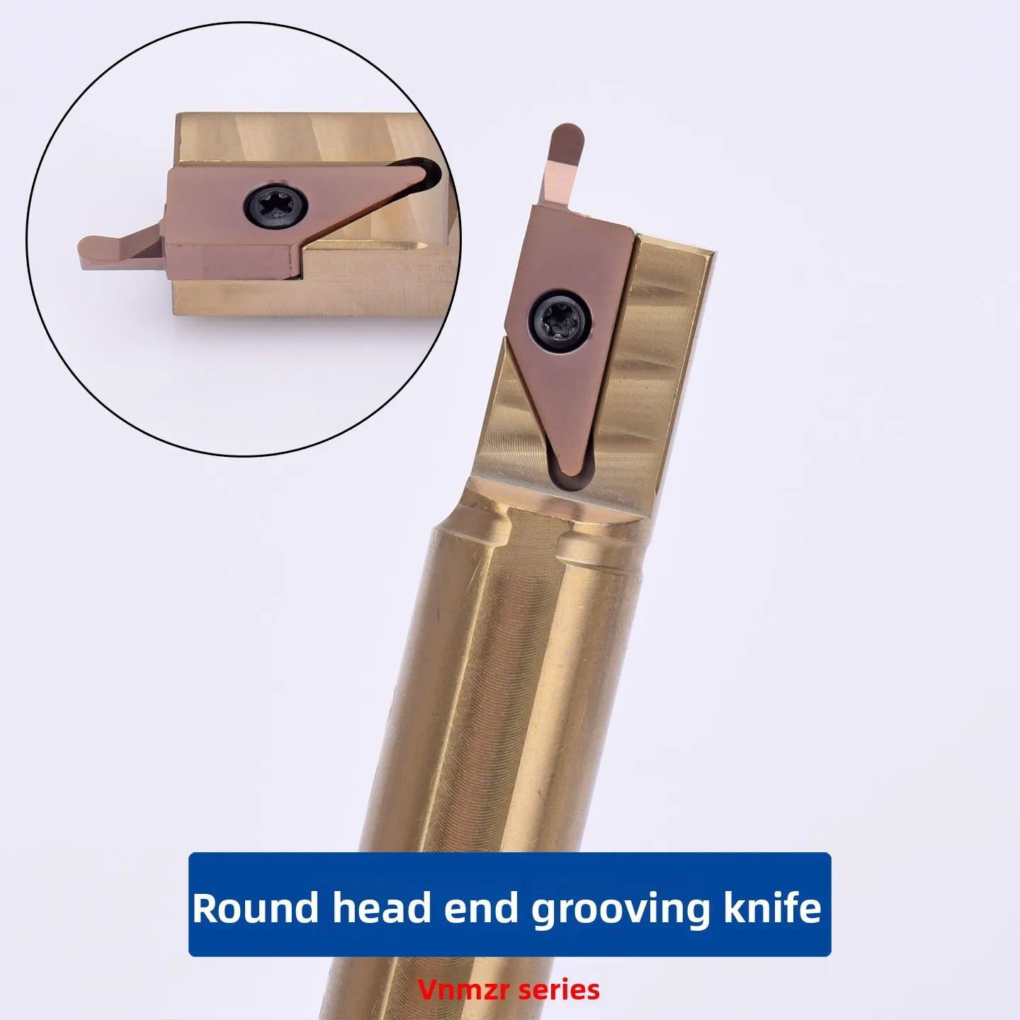
The image below shows the type of tooling geometry I evaluate when comparing Small Boring Tools, insert clearance, and internal cutting access.
!
How to Choose the Right Small Bore Boring Tool Nose Radius
I use a decision process rather than choosing a radius from surface-finish requirements alone. The insert nose radius must fit the bore, the radial depth of cut, and the mechanical limits of the boring bar.
1. Confirm the minimum bore and tool clearance
First, measure the finished bore diameter and determine how much space remains between the boring bar, insert corner, and hole wall. The insert nose radius is only one part of the required clearance; the insert shape, relief angle, lead angle, and holder geometry also matter.
For small-diameter internal boring, a practical starting range is often:
| Application condition | Typical starting nose radius |
|---|---|
| Very small bore or long overhang | 0.10–0.20 mm |
| General small-bore finishing | 0.20–0.40 mm |
| Short, rigid bar with adequate stock | 0.40–0.80 mm |
| Heavy internal roughing with sufficient clearance | 0.80 mm or larger |
These are starting points rather than universal limits. The minimum bore diameter for boring tools depends on the complete holder and insert geometry, not just the catalog radius. I always verify the manufacturer’s minimum bore specification before programming the tool.
2. Compare the radius with the radial depth of cut
The radial depth of cut must be large enough for the insert to cut continuously but not so large that the nose pushes against the bore wall. For a finishing pass, I commonly begin with a radial depth of cut that is at least 25% to 50% of the nose radius.
For example, if the insert nose radius is 0.40 mm, a finishing radial depth of cut around 0.10–0.20 mm may be workable on a rigid setup. If the remaining stock is only 0.05 mm radially, a 0.40 mm radius may rub instead of cutting cleanly, especially with a neutral or unfavorable tool orientation.
A 0.20 mm radius is more forgiving in that situation because it can engage a small amount of remaining stock without requiring heavy radial pressure. If the stock varies significantly, however, a small radius can become vulnerable to localized impact and edge chipping.
3. Check the feed rate against the radius
Feed rate selection by insert nose radius is commonly based on the theoretical roughness relationship:
[ R_a \approx \frac{f^2}{32r} ]
where:
- (R_a) is the theoretical arithmetic surface roughness in millimeters,
- (f) is feed per revolution in millimeters,
- (r) is nose radius in millimeters.
The formula does not account for vibration, built-up edge, tool deflection, material tearing, or chip evacuation, so I use it as a planning reference rather than a guaranteed result.
For a 0.40 mm nose radius at a feed of 0.08 mm/rev:
[ R_a \approx \frac{0.08^2}{32 \times 0.40} = 0.0005 \text{ mm} ]
That equals approximately 0.5 micrometers of theoretical Ra. In a real small bore, the measured result may be higher because the bar, chucking, spindle runout, and material condition contribute additional error.
If the same feed is used with a 0.20 mm radius, the theoretical roughness doubles:
[ R_a \approx \frac{0.08^2}{32 \times 0.20} = 0.001 \text{ mm} ]
This equals approximately 1.0 micrometer theoretical Ra. Therefore, a smaller radius can still produce an acceptable finish, but it usually requires a lower feed rate to match the theoretical finish of a larger radius.
4. Evaluate boring-bar rigidity and L:D ratio
Boring bar rigidity for small diameter holes is often more important than changing the insert radius. The length-to-diameter ratio, or L:D ratio, gives a quick indication of deflection risk:
[ L:D = \frac{\text{unsupported tool length}}{\text{bar diameter}} ]
As the overhang increases, stiffness falls sharply. For a cantilevered round bar, deflection is approximately proportional to the cube of the unsupported length:
[ \delta \propto \frac{L^3}{D^4} ]
This means a modest increase in overhang can create a substantial increase in tool movement. If I extend a bar from 60 mm to 90 mm without changing its diameter, the length-related deflection factor becomes:
[ \left(\frac{90}{60}\right)^3 = 3.375 ]
That is why a 0.80 mm nose radius may work on a short, solid setup but chatter on a slender boring bar. In the longer setup, I may reduce the radius to 0.20 or 0.40 mm, reduce feed, shorten the overhang, or use a larger-diameter bar before making further insert changes.
Small Nose Radius vs Large Nose Radius for Boring
A small nose radius reduces the amount of material contacted by the rounded edge. This generally lowers radial cutting force and makes the insert easier to position in a narrow bore. It is useful when the cut is light, the wall is thin, the bar is slender, or the hole is deep relative to its diameter.
A large nose radius increases the effective cutting-edge length and improves edge support. It can reduce theoretical surface roughness at the same feed and may improve wear distribution during stable production boring. However, it also increases cutting pressure and may cause the bar to deflect away from the cut, leaving an undersize or tapered bore.
| Nose radius | Main advantage | Main risk |
|---|---|---|
| 0.10–0.20 mm | Low radial force and narrow clearance requirement | Lower edge strength and possible chipping |
| 0.20–0.40 mm | Balanced finishing performance | Sensitive to unstable setups |
| 0.40–0.80 mm | Better edge strength and theoretical finish | Higher force, rubbing, and chatter risk |
| 0.80 mm or larger | Suitable for rigid roughing conditions | Often unsuitable for small bores and light cuts |
A smaller nose radius is not automatically better for small bore boring. I use it when rigidity, clearance, wall thickness, or remaining stock limits the use of a larger radius. When the setup is short and rigid, the material is stable, and the cut has enough radial engagement, the larger radius may provide better tool strength and finish consistency.
Selecting the Radius by Material
Material changes the balance between edge strength, cutting pressure, heat, and chip control. I do not use the same insert nose radius for aluminum, stainless steel, and hardened steel unless the cutting conditions are very similar.
Aluminum
For aluminum, I usually prioritize a sharp cutting edge, sufficient positive clearance, and chip evacuation. A 0.20–0.40 mm radius is often a practical starting range for small internal finishing, especially when the bore is narrow and the remaining stock is limited.
A larger radius can work in a rigid setup, but excessive edge contact may increase rubbing and built-up edge. I also check whether the insert has a polished or chip-control geometry intended for nonferrous materials.
Stainless steel
Stainless steel can generate high cutting pressure and work hardening when the insert rubs. A 0.20–0.40 mm radius is commonly easier to control in a small bore than a larger radius, provided the feed is sufficient to keep the edge cutting.
If the setup is rigid and the operation includes a stable semi-finishing pass, a 0.40–0.80 mm radius may improve edge support. I avoid reducing feed too far because rubbing can create heat, poor finish, and rapid edge wear.
Hardened steel
For hardened steel, edge preparation, insert grade, and cutting speed are as important as radius. A 0.20–0.40 mm radius can reduce cutting pressure in a small bore, but it may chip if the cut is interrupted or the workholding allows movement.
When the bar is short and the stock is consistent, a 0.40–0.80 mm radius can provide better edge support. I would not increase the radius to solve chipping if the actual cause is excessive runout, an interrupted cut, or an insert grade that is unsuitable for hardened material.
How Nose Radius Affects Chatter, Vibration, and Deflection
A larger nose radius can reduce surface roughness in a stable operation, but it does not automatically prevent chatter. Because the radius increases contact length and cutting force, it may intensify vibration when the boring bar has a high L:D ratio.
When I see repeating chatter marks, I check the boring bar diameter, unsupported length, toolholder clamping, insert seating, spindle condition, workholding, and coolant delivery before changing the insert radius. A smaller radius can reduce radial pressure, but it cannot correct a loose chuck, a weak fixture, excessive runout, or poor chip evacuation.
I use the following correction sequence:
- Reduce unsupported overhang and increase bar diameter where possible.
- Confirm that the boring bar is clamped securely and aligned on center.
- Reduce radial depth of cut if the insert is pushing against the wall.
- Adjust feed and speed in controlled increments rather than changing several variables.
- Test a smaller radius if the setup remains stable but cutting pressure is excessive.
- Improve chip evacuation before increasing nose radius or feed.
This approach prevents a nose-radius change from masking a structural problem.
Practical CNC Selection Workflow
I use this workflow when preparing a new small-bore operation:
- Record the bore data. Write down finished diameter, bore depth, stock allowance, wall thickness, and tolerance.
- Calculate the L:D ratio. Use the unsupported length and actual bar diameter, not the overall tool length.
- Read the insert code. Confirm the nose-radius symbol, relief angle, hand, chipbreaker, and grade.
- Select an initial radius. Start with 0.20–0.40 mm for small finishing bores, then increase only when rigidity and stock support it.
- Set the radial cut. Keep the finishing depth large enough to cut continuously but small enough to avoid excessive pressure.
- Calculate a starting feed. Use the roughness equation, then reduce feed if vibration or rubbing appears.
- Set tool compensation carefully. Enter the correct nose-radius value in the CNC tool offset table and verify orientation or tip-direction settings.
- Run a test cut. Measure bore diameter, roundness, taper, surface roughness, and insert condition.
- Change one variable at a time. Adjust radius, feed, speed, or depth of cut separately so the result is traceable.
Tool-nose compensation is especially important when the insert radius is changed from 0.20 mm to 0.40 mm or 0.80 mm. Incorrect compensation can create a measurable profile error even when the mechanical setup is stable.
Troubleshooting Matrix for Small Bore Boring
| Symptom | Likely cause | Radius-related correction | Other correction required |
|---|---|---|---|
| Chatter marks | Excessive force or weak bar | Try a smaller radius | Reduce overhang, improve clamping |
| Poor surface finish | Feed too high for radius | Increase radius if stable or reduce feed | Check built-up edge and runout |
| Insert chipping | Radius too small for interrupted load | Try a larger radius | Use suitable grade and reduce impact |
| Rubbing or burnishing | Too little radial stock | Use a smaller radius | Increase radial cut or correct tool position |
| Oversize bore | Bar deflection or thermal movement | Smaller radius may reduce force | Check rigidity, compensation, and measurement |
| Tapered bore | Deflection changes with depth | Reduce radius if cutting pressure is high | Shorten overhang and verify alignment |
| Poor chip evacuation | Chipbreaker or coolant issue | Radius change may have limited effect | Improve coolant direction and chip control |
This matrix shows why nose-radius changes cannot solve every boring problem. If the workpiece moves, the bar deflects, or chips recut inside the bore, the insert radius is only one part of the process.
Small Boring Tools and KEUE CNC
When I compare Small Boring Tools for production or custom work, I review more than the insert radius. I also check the available bar diameters, holder geometry, insert codes, coatings, replacement availability, and technical documentation.
KEUE CNC was established in 2011 in Wenling, Taizhou, China, and supplies CNC cutting tools including turning tools, inserts, milling cutters, drilling products, and tooling systems. Its product range includes small bore boring tools, and the company describes an independent R&D and design team, imported factory equipment, and customization of coating, size, and precision.
For a custom small-bore application, the useful information to provide is the finished bore diameter, bore depth, material grade, tolerance, surface-finish target, machine type, spindle speed range, and available tool overhang. KEUE CNC also lists a quotation and delivery process for customized products, with stated quotation timing of 3–7 days. I would still request a drawing, insert recommendation, and sample-cut parameters before approving a production batch.
Final Checks Before Production
Before releasing the job, I confirm that the selected nose radius fits the actual insert pocket and does not contact the opposite bore wall. I verify the tool offset, center height, insert seating, spindle runout, and measured stock allowance.
I also compare the calculated feed with the machine’s practical stability. For example, a 0.40 mm radius at 0.08 mm/rev may produce a favorable theoretical roughness value, but a 90 mm overhang on a 10 mm bar may require a lower-force 0.20 mm radius, reduced depth of cut, or a different bar design.
The final decision should be based on the complete cutting system: bore diameter, bar diameter, L:D ratio, radial depth, feed, material, workholding, chip evacuation, and tolerance. If those conditions are controlled, the radius can be selected with predictable trade-offs rather than trial and error.
Conclusion
The correct Small Bore Boring Tool Nose Radius: How to Choose the Right Size depends on the relationship between bore diameter, bar rigidity, depth of cut, feed rate, material, and surface-finish requirements. I normally begin with a 0.20–0.40 mm radius for small-bore finishing, use 0.10–0.20 mm when clearance or rigidity is severely limited, and consider 0.40–0.80 mm only when the bar and workpiece can absorb the additional cutting force.
A larger radius can improve edge strength and theoretical surface finish, while a smaller radius can reduce radial pressure and fit light or deep internal cuts. Neither choice will correct poor workholding, excessive overhang, incorrect compensation, or blocked chip evacuation.
For the next job, I recommend measuring the bore and stock, calculating the L:D ratio, selecting the radius from the available clearance, setting feed from the radius-based roughness relationship, and confirming the result with a test cut. That process provides a practical way to choose the right small bore boring tool nose radius for CNC machinists and small CNC shops.