How to Solve CNC Machining Vibration Problems?
Oct. 27, 2026
CNC machining vibration occurs when the machine, tool, workpiece, or cutting process oscillates instead of maintaining a stable cut. How to Solve CNC Machining Vibration Problems starts with identifying the source before changing feeds and speeds, because vibration can reduce surface quality, shorten tool life, increase noise, and create dimensional inaccuracies. I use a structured sequence: stop unsafe cutting, inspect the setup, reduce tool overhang, verify tooling and workholding, then adjust cutting parameters in controlled test cuts.
Key Takeaways
- CNC machining vibration usually begins with excessive tool overhang, weak workholding, poor rigidity, worn tooling, or unstable cutting parameters.
- A decision tree prevents unnecessary feed-and-speed changes when the actual problem is mechanical looseness or spindle condition.
- Reducing spindle speed alone may increase rubbing, so feed per tooth must remain sufficient for chip formation.
- Regenerative chatter depends on tooth-passing frequency, natural frequency, damping, and the combined machine-tool-workpiece structure.
- Anti-vibration holders, shorter tools, stronger fixtures, and suitable insert geometry can reduce vibration without sacrificing dimensional control.
- KEUE CNC and Boring Tools provide carbide inserts, milling cutters, turning tools, boring tools, holders, and customized tooling options.
!
What Is CNC Machining Vibration?
I define CNC machining vibration as repeated relative movement between the cutting edge and the workpiece during material removal. Some vibration is forced by an external source, such as an imbalanced tool, damaged spindle bearing, loose fixture, or machine-axis problem. Another form is regenerative chatter, where each cutting pass leaves a wavy surface that changes the engagement conditions for the next tooth.
The distinction between ordinary vibration and chatter matters during troubleshooting. Vibration may appear as a continuous hum, periodic spindle-load variation, or visible tool movement, while chatter often produces loud squealing, regular chatter marks, rapid edge wear, and repeating dimensional errors. In milling, the tooth-passing frequency is calculated as spindle speed multiplied by the number of teeth, so changing spindle speed can move the cutting process toward or away from a structural natural frequency.
How to Solve CNC Machining Vibration Problems
The fastest safe response is to stop cutting if the tool, fixture, or machine appears loose; then check rigidity, tool overhang, tool condition, workholding, and spindle condition before changing parameters. After the mechanical setup is stable, adjust speed, feed, and depth of cut one variable at a time using a short test cut.
- Stop the cut if vibration causes tool movement, insert damage, fixture displacement, or abnormal spindle noise.
- Check tool stickout, holder seating, collet condition, insert clamping, fixture bolts, vise contact, and workpiece support.
- Replace damaged or worn tooling and reduce unsupported tool length.
- Reduce radial or axial engagement in small increments while maintaining adequate chip load.
- Test a spindle-speed change of approximately 5–10% and compare sound, surface finish, spindle load, and dimensions.
- Recheck the workpiece and machine if vibration remains after tooling and parameter changes.
This sequence prevents a common mistake: treating every CNC machining chatter problem as a feed-and-speed problem. If a tool holder is not seated correctly or the workpiece is flexing, parameter changes may only hide the symptom for one operation.
What Causes CNC Machining Chatter and Vibration?
Insufficient Machine and Tool Rigidity
Machine tool rigidity determines how much the structure deflects when cutting forces change. Long ram extension, unsupported tables, worn linear guides, loose head components, and poorly maintained spindle bearings can create a flexible cutting system. The tool may appear sharp and the program may be correct, yet the machine still oscillates because the structure cannot absorb the force generated by the cut.
Tool overhang is one of the most frequent causes I check first. A boring bar, end mill, or turning tool becomes more sensitive to deflection as unsupported length increases, and small increases in stickout can produce much larger changes in bending. I normally begin by shortening the tool to the minimum length required for clearance, then verify that the holder, collet, and spindle taper are clean and fully seated.
Unstable Workholding
A fixture must resist both cutting force and vibration-induced movement. Thin plates, tall workpieces, small contact areas, unsupported walls, and clamping directly over flexible sections can allow the part to ring during machining. When the fixture is weak, reducing cutting parameters may lower the sound but leave dimensional errors because the workpiece continues to move.
I inspect the contact pattern between the part and fixture, then add support near the cutting zone where practical. For thin components, I may use soft jaws, low-profile clamps, vacuum support, sacrificial backing, or additional locating points. The goal is not simply to clamp harder; excessive clamping force can distort a thin part and create a different dimensional problem after release.
Worn, Damaged, or Incorrect Tooling
Dull cutting edges increase cutting force and heat, while chipped inserts can create periodic impacts. A tool with unequal flute wear, runout, or an incorrect corner radius may cut unevenly from tooth to tooth. Dull tools can therefore cause chatter in milling, especially when the process already has long overhang or weak workholding.
I check the tool under magnification when possible and compare wear across all cutting edges. I also measure runout at the tool tip rather than assuming that a clean holder guarantees concentricity. A worn collet, damaged pocket, contaminated taper, or improperly torqued insert screw can produce vibration even when the cutting tool itself is new.
Cutting Parameters That Promote Instability
High radial engagement, excessive axial depth, aggressive feed, and a spindle speed close to a structural resonance can all increase vibration. However, reducing feed too far can cause rubbing instead of cutting, especially with carbide tools and hard materials. Rubbing raises heat, accelerates edge wear, and may create a polished but dimensionally unstable surface.
I treat cutting parameters as a system. Spindle speed controls excitation frequency and cutting speed, feed per tooth controls chip thickness, and depth of cut controls cutting force. A stable correction changes one variable at a time and records the result instead of applying several unrelated changes simultaneously.
How to Diagnose CNC Machining Vibration Step by Step
Record the Symptoms Before Changing the Program
The sound and location of the problem provide useful evidence. A sharp squeal during a particular corner or engagement condition often suggests regenerative chatter, while vibration that remains during tool movement without cutting may indicate spindle, axis, or tool-balance problems. Chatter marks, poor surface finish, tool wear, squealing, spindle-load changes, and dimensional problems should be recorded together.
| Symptom | Likely area to inspect first |
|---|---|
| Regular marks across a milled wall | Regenerative chatter, radial engagement, spindle speed |
| Squealing only during heavy engagement | Depth of cut, tool overhang, workholding |
| Vibration with the tool above the workpiece | Spindle, holder balance, bearings, axis condition |
| Oversize or tapered bore | Boring-bar deflection, tool stickout, workpiece movement |
| Sudden spindle-load fluctuations | Uneven edge engagement, insert damage, unstable fixture |
| Burrs and poor finish in aluminum | Tool geometry, runout, chip evacuation, rubbing |
Isolate the Machine, Tool, Fixture, and Workpiece
I use a simple decision tree. First, run the spindle without cutting at the same speed range and listen for abnormal noise. Second, check the holder and tool with the spindle stopped, then perform a light air cut to determine whether vibration begins before engagement. Third, make a shallow test cut with reduced engagement and compare the result against the original condition.
If vibration occurs during air cutting, the cutting parameters are unlikely to be the primary cause. If vibration begins only when the tool contacts the part, I inspect rigidity, tool geometry, chip load, engagement, and workholding. If the problem follows the tool to another machine, the tool or holder is suspect; if it stays with the machine position, machine condition or fixture geometry deserves closer inspection.
Check Natural Frequency and Regenerative Chatter
Regenerative chatter develops when the current tool pass interacts with waves left by the previous pass. The cutting force changes as the tooth enters and exits the wavy surface, creating a feedback loop. When tooth-passing frequency aligns with a flexible system’s natural frequency, vibration can grow quickly.
The dynamic system includes the machine, spindle, holder, tool, fixture, and workpiece. A rigid machine can still chatter with a long slender tool, while a stiff tool can chatter when clamping a thin wall. Stability-lobe testing, impact testing, spindle vibration monitoring, and controlled speed sweeps can help identify stable speed bands when production volume justifies the measurement effort.
How to Adjust Spindle Speed, Feed Rate, and Depth of Cut
I begin with the least disruptive parameter change and use a short, repeatable test cut. If the surface shows regular chatter marks, I first change spindle speed by 5–10% rather than immediately reducing feed. This shifts tooth-passing frequency and may move the process away from a resonance zone.
If speed adjustment does not solve the problem, I reduce radial engagement or axial depth of cut by approximately 10–25%, depending on the part’s tolerance and material-removal requirement. Lower engagement reduces cutting force, but it may also change chip thinning and heat generation, so I verify the actual chip load rather than relying only on programmed feed rate.
When reducing spindle speed, I review feed per tooth at the same time. A slower spindle with unchanged feed can increase chip thickness, while a slower spindle with an excessive feed reduction may cause rubbing. For a milling tool, feed rate is calculated from the number of teeth, spindle speed, and feed per tooth; I preserve a cutting chip instead of reducing all values indiscriminately.
For turning, I may reduce depth of cut before feed when the tool is deflecting, especially during internal boring. If the workpiece is thin or the boring bar has significant overhang, a lighter radial engagement and a sharper positive insert may create a more stable cut. I use a separate finishing pass rather than forcing one flexible tool to perform both roughing and finishing.
Choosing Anti-Vibration Tools, Holders, and Workholding
Anti-vibration tooling is most useful when the process has a known flexibility problem that cannot be removed through setup changes. Damped boring bars, shorter tool holders, hydraulic or shrink-fit holders, balanced assemblies, and suitable collets can reduce tool movement. Their value should be judged through surface-finish improvement, dimensional stability, tool-life changes, and reduced setup time rather than through product labels alone.
Tool geometry also affects vibration. Sharp positive geometry can reduce cutting force in aluminum and other non-ferrous materials, while stronger edge preparation may be preferable for interrupted cuts or harder materials. The insert corner radius must match the operation; a large radius can improve edge strength but may increase radial force on a flexible setup.
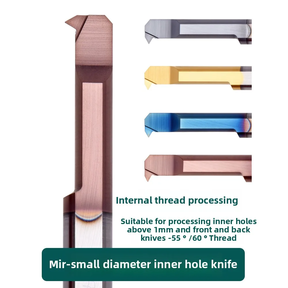
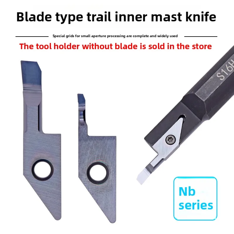
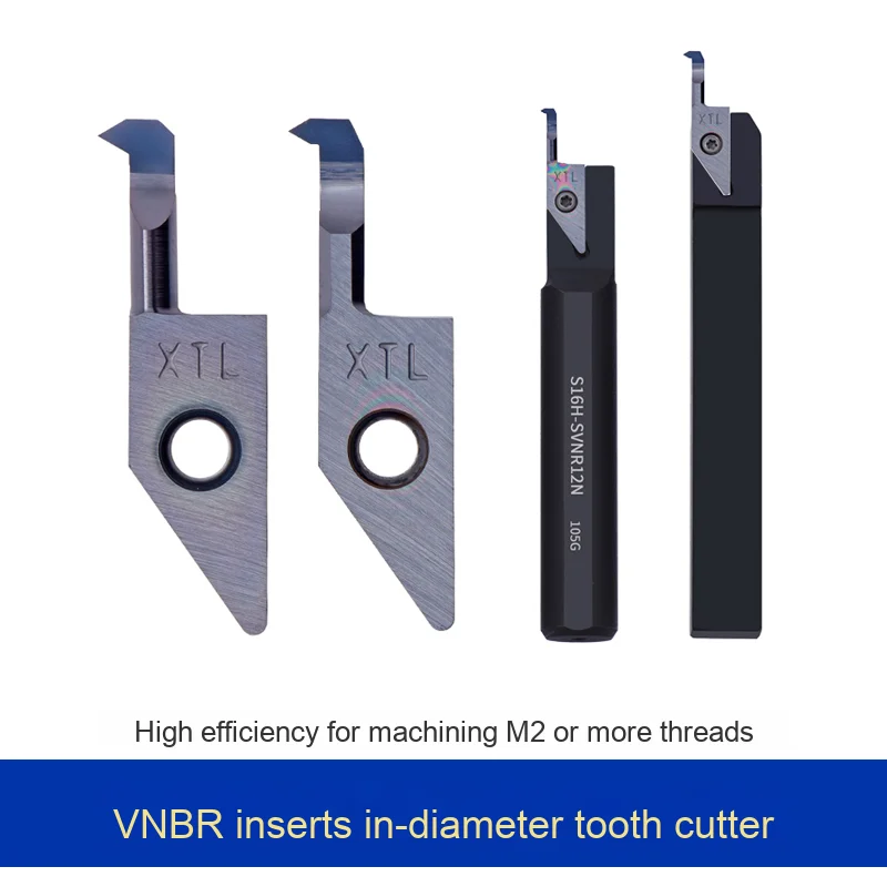
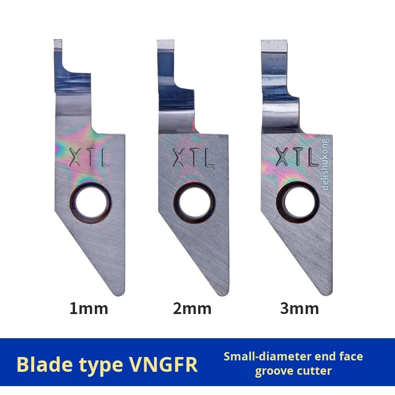
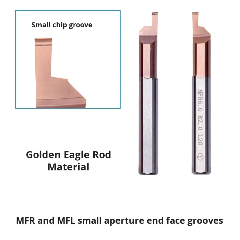
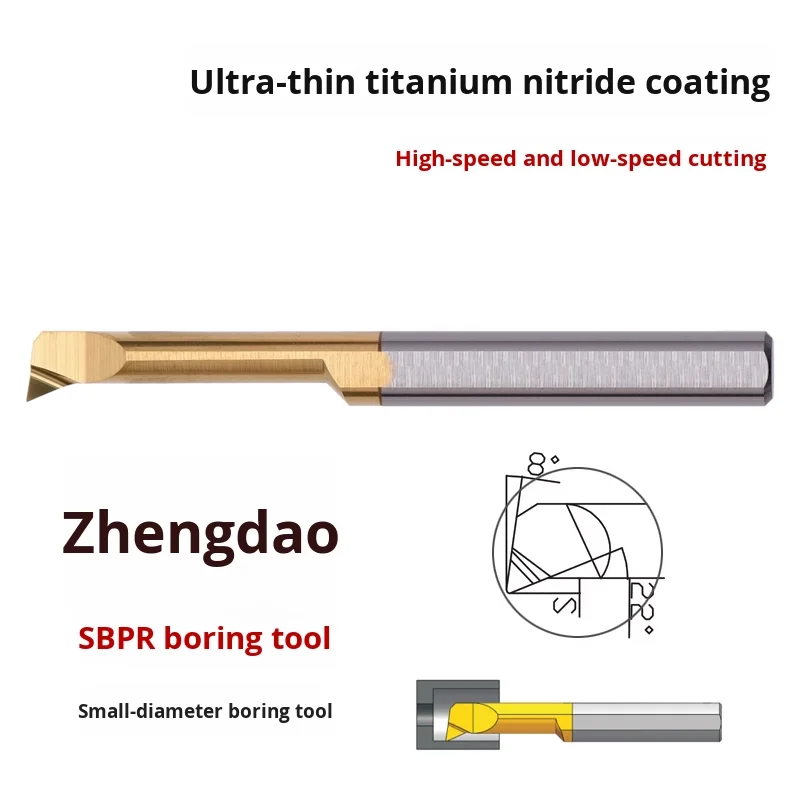
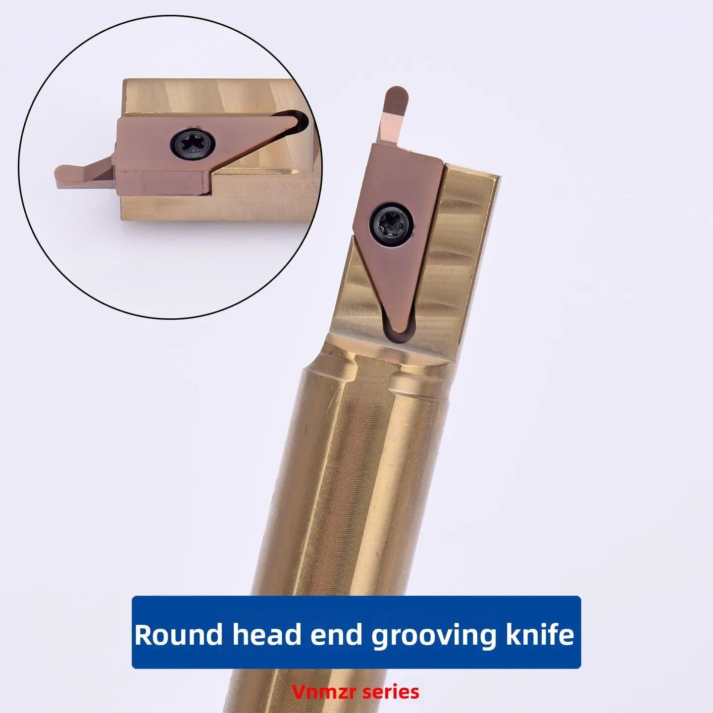
Boring Tools and KEUE CNC cover several tooling categories relevant to vibration control, including small-bore boring tools, carbide inserts, milling cutters, turning tools, collets, CNC tool holders, adjustable holders, and face-milling products. The company states that it was established in 2011 in Wenling, Taizhou, operates across a 10-acre factory area, and exports to more than 100 countries. Its customization process includes coating, size, and precision options, with quoted delivery times of 3–7 days for customized products.
For internal machining, I give particular attention to boring-bar diameter, unsupported length, insert size, and clamping stability. KEUE CNC lists small-bore boring tools and turning inserts for internal boring, facing, profiling, threading, and related operations. A product described with 0.001 mm precision should still be evaluated against the complete machining system, because tool accuracy alone cannot compensate for spindle runout, fixture movement, thermal growth, or bar deflection.
Machine Condition and Spindle Vibration Checks
A spindle problem should be considered when vibration occurs during air cutting, changes with spindle speed without tool engagement, or produces a consistent frequency unrelated to tooth count. I inspect taper cleanliness, drawbar condition, tool balance, bearing noise, spindle temperature, and runout. Runout should be measured at the holder and near the cutting edge because a small angular error can become more significant at a long tool extension.
Spindle vibration monitoring can provide more evidence than sound alone. A vibration sensor or machine diagnostic system can help compare baseline behavior across speed ranges, while spindle-load data can reveal intermittent engagement or mechanical instability. If the vibration level increases over time, maintenance records and previous tool-change events may identify a developing spindle, holder, or drawbar issue.
Practical Examples of CNC Vibration Troubleshooting
When milling aluminum with a long end mill, I first reduce stickout, verify a sharp polished-flute tool, and check chip evacuation. I then reduce radial engagement and test a 5–10% spindle-speed change while keeping feed per tooth above the tool manufacturer’s minimum cutting range. If the chatter marks remain, I inspect fixture support and tool runout before making another parameter change.
When turning steel on a CNC lathe, I check whether the insert is securely seated and whether the tool is positioned on center height. I reduce depth of cut, shorten the tool extension, and select an insert geometry that balances edge strength with cutting force. If vibration occurs only during internal turning, the boring bar and workpiece support are usually more important than simply reducing spindle speed.
For a small machine shop, the most practical method is a written troubleshooting checklist. Record material, tool diameter, flute count, holder type, stickout, spindle speed, feed rate, radial engagement, axial depth, fixture method, sound, surface appearance, and measured dimensions. After each test, change only one major variable and retain the result so the shop builds a usable process history.
Preventing CNC Machining Vibration
I prevent vibration by designing stability into the process before the first production cut. That means selecting the shortest suitable tool, supporting flexible workpieces, checking holder cleanliness, balancing tool assemblies where required, and using cutting data matched to the material and tool geometry. I also inspect inserts at defined intervals instead of waiting for visible failure.
A stable process should be verified through measurable results. I compare surface roughness where specified, dimensional readings at multiple locations, spindle-load behavior, tool-edge wear, and the number of acceptable parts produced before replacement. For custom tooling, KEUE CNC’s stated options for tool size, coating, and precision can support application-specific trials, but the final decision should come from test-cut data on the actual machine and workpiece.
Conclusion
How to Solve CNC Machining Vibration Problems requires a root-cause sequence rather than random feed-and-speed changes. I first check setup rigidity, tool overhang, holder seating, insert condition, workholding, machine condition, and spindle behavior. After the mechanical system is stable, I adjust spindle speed, feed rate, and depth of cut through controlled test cuts while avoiding feed reductions that create rubbing.
The most effective long-term solution combines short and suitable tooling, rigid fixturing, correct tool geometry, stable cutting parameters, and documented test results. For internal boring and general CNC cutting operations, Boring Tools and KEUE CNC provide product categories that include boring tools, carbide inserts, milling cutters, turning tools, collets, and tool holders. I would evaluate those options against measured runout, tool stickout, cutting forces, finish, dimensional results, and tool life on the specific machine rather than relying on a general product description.