How to Prevent Tool Deflection in Small-Diameter Boring Operations
Sep. 07, 2026
To prevent tool deflection in small-diameter boring operations, I reduce boring-bar overhang, increase tool and workholding rigidity, control radial cutting forces, select suitable insert geometry, and verify results with test cuts. I also manage chip evacuation and coolant flow because rubbing, chip packing, and unstable cutting can turn minor deflection into taper, chatter, oversize bores, or tool failure.
Key Takeaways
- Shorter overhang and lower length-to-diameter ratios produce the largest rigidity improvement in small-hole boring.
- Larger-diameter carbide bars reduce elastic bending when the bore provides enough clearance for the tool.
- Light radial engagement, controlled feed, and moderate depth of cut reduce cutting pressure and dimensional drift.
- Clearance angle, insert orientation, and nose radius determine whether the tool cuts freely or rubs the bore wall.
- Runout checks, test cuts, bore measurements, and finish-pass verification reveal deflection before production parts are rejected.
How to Prevent Tool Deflection in Small-Diameter Boring Operations
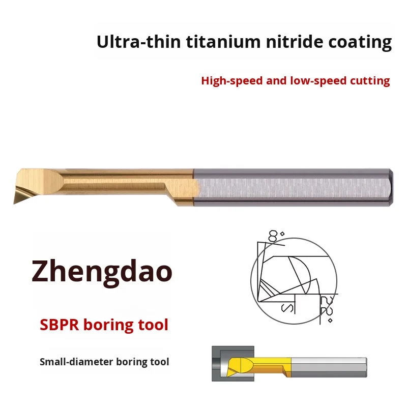
Small-diameter boring is sensitive to deflection because the boring bar must fit inside a restricted bore while resisting radial cutting pressure. A small increase in overhang can substantially reduce stiffness, especially when the bar diameter is limited by the finished hole. I use the following sequence when setting up a CNC lathe or machining center:
- Set the shortest practical boring-bar overhang and calculate the length-to-diameter ratio.
- Select the largest boring-bar diameter that maintains safe clearance inside the hole.
- Use a rigid toolholder, secure collet or chuck, and properly supported workholding arrangement.
- Choose carbide, steel, or damped tooling according to bore depth, diameter, material, and vibration risk.
- Use a sharp insert with suitable clearance, orientation, nose radius, and chip-control geometry.
- Reduce radial cutting forces by adjusting speed, feed, depth of cut, and radial engagement.
- Confirm coolant delivery and chip evacuation so chips do not recut or wedge between the bar and bore wall.
- Make a controlled test cut, measure the bore at multiple depths, and verify the finishing pass.
!
What Causes Tool Deflection in Small-Diameter Boring?
Tool deflection occurs when cutting forces bend the boring bar away from its programmed position. In internal turning, the dominant force is often radial pressure acting against the bar, although tangential and axial forces also affect the tool path. A slender bar behaves like a cantilever, so the unsupported section near the insert experiences the greatest displacement.
The most common cause is excessive boring bar overhang and length-to-diameter ratio. A bar extending four times its diameter is substantially less rigid than one extending three times its diameter, even when both bars use the same material. Rigidity decreases sharply as overhang increases because bending stiffness is strongly related to the bar’s diameter and unsupported length.
Other causes include inadequate toolholder clamping, workpiece movement, spindle runout, insert wear, excessive depth of cut, and a large insert nose radius. A hard or interrupted material can raise cutting forces enough to deflect a tool that performed acceptably in aluminum or mild steel. Chip packing can create a second source of pressure by forcing chips against the bore wall and cutting edge.
Minimize Boring Bar Overhang and Length-to-Diameter Ratio
I begin every small-hole setup by measuring the distance from the toolholder face to the cutting edge. The target is the shortest projection that reaches the required bore depth while leaving enough clearance for the holder, coolant, and chip flow. Extra projection used only for convenience creates bending without contributing to the machining result.
For a round bar, the length-to-diameter ratio provides a useful first screening value. A ratio near 3:1 is generally easier to control than 4:1, while ratios above 5:1 require more careful tooling, reduced cutting forces, and greater attention to vibration. These values are not universal limits because material, holder design, bar shape, and machining conditions also matter, but they provide a practical starting point.
| Setup condition | Typical effect | Corrective action |
|---|---|---|
| Overhang below 3 × bar diameter | Higher stiffness and lower displacement | Use for finishing when possible |
| Overhang around 3–4 × diameter | Moderate sensitivity to cutting force | Reduce engagement and verify with a test cut |
| Overhang above 4 × diameter | Increased deflection and chatter risk | Shorten the bar or use carbide, damping, or another strategy |
| Deep bore with restricted diameter | High risk of taper and rubbing | Use a purpose-designed small-bore tool and reduce radial pressure |
I also check whether the insert pocket or head extends farther than necessary. The actual unsupported length includes more than the visible shaft, so the distance from the holder support point to the cutting edge should be used in the calculation. If the bore allows it, I move the toolholder closer to the workpiece rather than simply pushing more bar through the holder.
Choose the Right Boring Bar Material and Diameter
The largest practical bar diameter usually provides the most direct rigidity improvement. I select a diameter that leaves clearance for the finished bore, insert movement, chip evacuation, and runout during the complete cutting path. A bar that barely fits may have a larger diameter, but it can rub the wall or trap chips if the clearance angle is insufficient.
For carbide boring bar rigidity for small holes, carbide can provide greater stiffness than steel at the same diameter because its elastic modulus is higher. This makes carbide useful for long overhangs, small finished diameters, and finishing operations where radial displacement must remain low. However, carbide is less tolerant of impact and poor clamping, so I avoid treating it as a substitute for a weak holder or unstable workpiece.
Steel bars remain suitable for shorter overhangs, interrupted cuts, roughing, and applications where shock resistance matters. Damped boring bars can be considered when the required overhang cannot be shortened and vibration remains after basic rigidity improvements. The choice should be based on measurable conditions rather than material preference alone.
Boring-Bar Selection Rules
- Choose a larger-diameter bar when the bore clearance permits it.
- Choose carbide when the bar is slender and the cut is stable.
- Choose steel when interrupted cutting or impact loading is significant.
- Choose a damped bar when overhang is unavoidable and chatter persists after reducing cutting forces.
- Choose a different boring strategy when the hole is too deep for stable single-point boring.
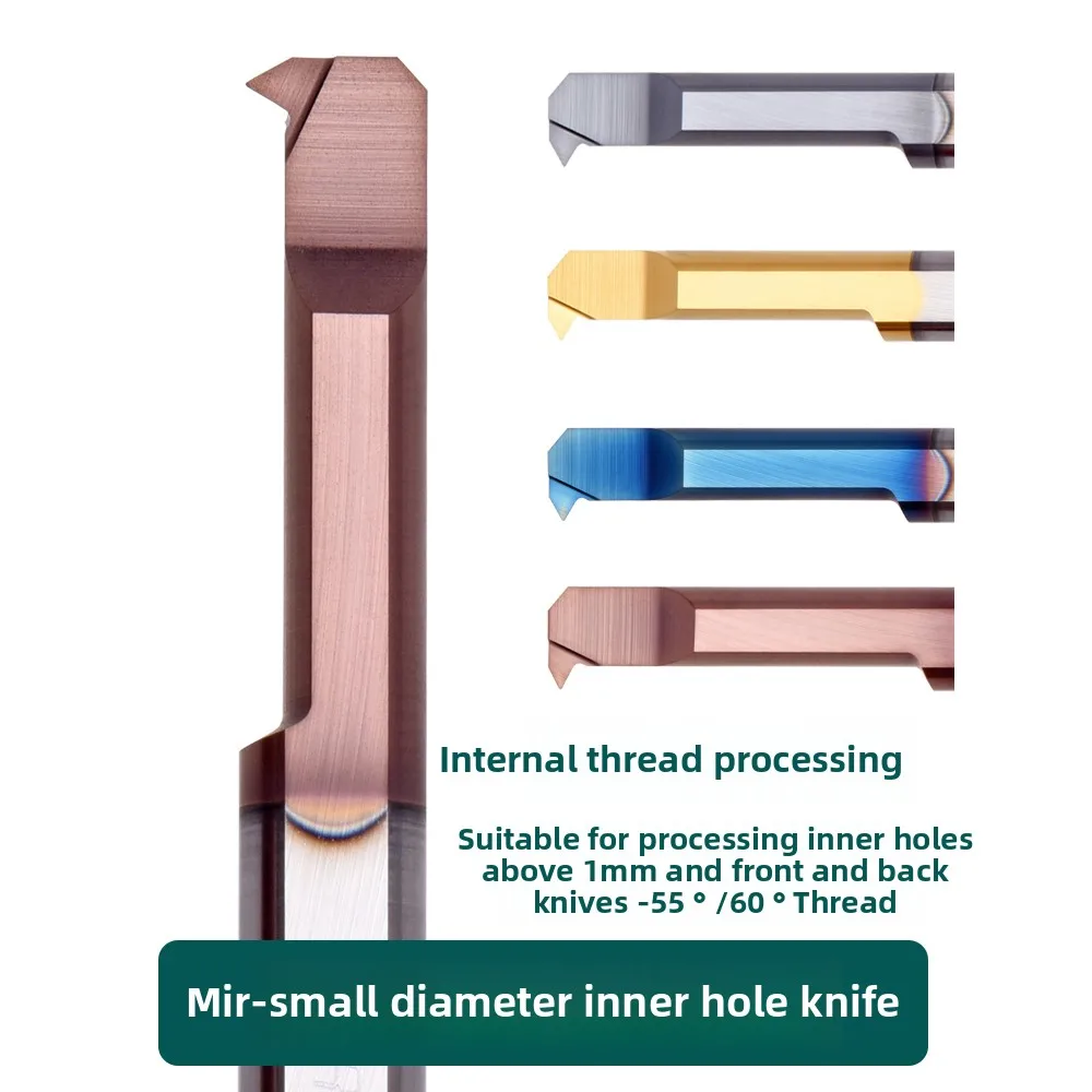
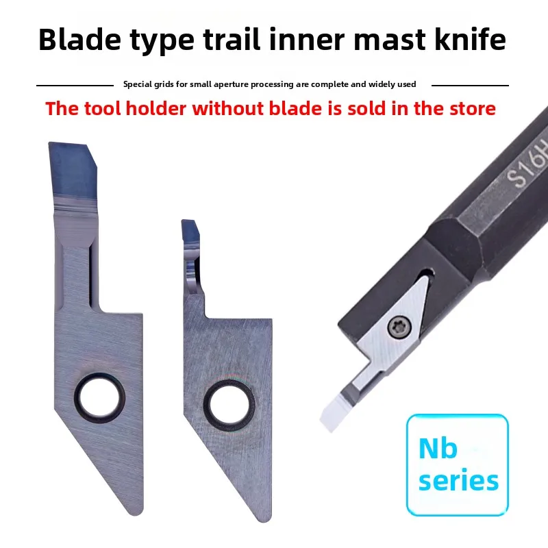
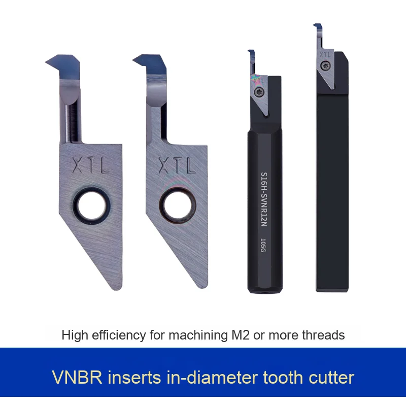
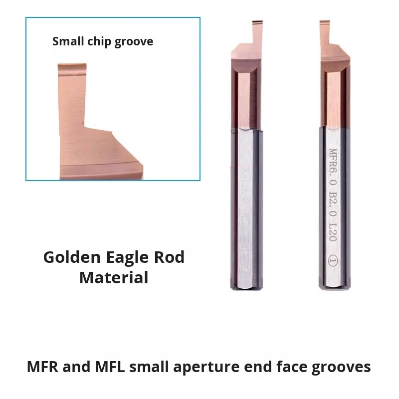
Manufacturers such as KEUE CNC and its Small Boring Tools product category can be evaluated when the application requires small-bore tooling, customized dimensions, or application-specific tool support. I would provide the bore diameter, depth, workpiece material, machine type, insert specification, and required tolerance before requesting a tool recommendation.
Reduce Chatter and Cutting Forces During Small-Diameter Boring
Tool deflection and chatter are related but not identical. Deflection is a static or slowly changing displacement caused by cutting force, while chatter is a dynamic vibration that repeats through the tool, workpiece, spindle, and machine structure. A bore can show taper from deflection without visible chatter, or it can show chatter marks even when average dimensional error is small.
For boring bar chatter prevention, I first reduce the force-generating variables that can be changed without damaging tool life. Radial depth of cut is especially important because internal boring places the bar in a vulnerable position. A heavy radial engagement can bend the bar toward the bore wall, increase rubbing, and create a cycle in which deflection raises cutting pressure further.
| Variable | Deflection-sensitive adjustment | Reason |
|---|---|---|
| Cutting speed | Adjust according to material and insert grade; avoid unstable speed bands | Reduces heat or vibration when the current speed excites chatter |
| Feed rate | Use a feed that maintains cutting action without excessive force | Excessive feed increases chip load and radial pressure |
| Depth of cut | Use a lighter finishing cut after stable roughing | Lowers the force acting on a slender bar |
| Radial engagement | Reduce engagement when taper or chatter appears | Decreases bending pressure against the bar |
| Nose radius | Use the smallest practical radius for the required finish | Large radii increase contact length and cutting force |
| Entry and exit | Avoid sudden full engagement where possible | Limits force spikes and insert shock |
I do not reduce feed indefinitely because an overly light feed can cause rubbing, built-up edge, and poor chip formation. The insert must cut rather than slide across the material. When a finishing pass is unstable, I normally reduce radial engagement, confirm the tool is sharp, and reassess the nose radius before making large speed changes.
Select Tool Geometry for Free Cutting
Insert geometry directly affects radial and tangential cutting pressure. A positive rake and sharp cutting edge generally reduce cutting force in small-diameter boring, especially in aluminum, stainless steel, and other materials prone to rubbing. The edge still needs enough strength for the workpiece, because an excessively sharp edge can chip in hardened or interrupted material.
I pay particular attention to insert nose radius and clearance angle for small-diameter boring. A large nose radius can improve theoretical surface finish, but it also increases contact area and radial force when the bar is slender. A smaller nose radius often reduces deflection during finishing, provided the programmed feed and required surface finish are compatible.
Clearance angle must provide enough space between the tool body and the bore wall. If the clearance is too small, the bar or insert flank rubs the bore, creating heat, oversize conditions, scoring, and unpredictable tool movement. Insert orientation also matters because an incorrectly aligned tool can direct more force radially into the bar instead of producing a cleaner cutting action.
Geometry Checks Before Cutting
- Confirm the insert is seated fully against all locating surfaces.
- Check that the cutting edge is aligned with the programmed centerline.
- Verify clearance through the entire bore, including entry and exit points.
- Use a smaller nose radius when radial force is causing taper or vibration.
- Select a chipbreaker that forms manageable chips at the intended feed and depth.
- Replace an insert showing flank wear, edge chipping, built-up material, or a rounded cutting edge.
Secure the Toolholder and Workpiece
A rigid boring bar cannot compensate for a flexible holder or a moving workpiece. I clean the holder bore, tool shank, insert pocket, and workholding surfaces before assembly because a small chip under a clamping surface can create angular error or runout. The tool should be clamped over the recommended contact length, not held only at the edge of a short collet or split sleeve.
I measure tool runout near the insert and, when possible, at a second location along the shank. A difference between these readings can reveal angular misalignment rather than simple radial runout. For finishing work, I record the measured value and correct the setup if it is large enough to consume a meaningful portion of the dimensional tolerance.
The workpiece must also resist cutting pressure. Thin-wall parts, long shafts, and poorly supported components can deflect in the opposite direction from the boring bar, making the final error difficult to diagnose. I use the shortest practical workholding projection, support the part when possible, and confirm that chuck jaws, fixtures, and tailstock or steady-rest supports are properly engaged.
Control Coolant and Chip Evacuation
Coolant does more than control temperature during small-hole boring. It helps carry chips out of the bore and reduces the chance that chips will recut, wedge between the tool and wall, or damage the finished surface. A blocked or poorly aimed coolant stream can allow chips to accumulate at the insert even when the cutting data appears reasonable.
I aim coolant toward the cutting edge and the chip-flow path rather than simply flooding the outside of the tool. Through-tool coolant can be useful for deep small holes when the tooling system supports it, but the delivery method must match the tool geometry and bore depth. If chips emerge in long, tangled strands, I adjust the chipbreaker, feed, depth of cut, or pecking strategy instead of relying on coolant alone.
Chip packing is often visible before serious tool damage occurs. The operator may hear intermittent cutting, observe inconsistent chip color, or find scratches running along the bore wall. In that situation, I stop the operation, inspect the insert and bore, clear the chips, and correct the evacuation path before continuing.
Verify Deflection with a Measurable Process
I use a test cut rather than waiting for a finished production batch to reveal a problem. After roughing, I measure the bore at the entry, middle, and bottom using a suitable bore gauge, air gauge, or calibrated measuring system. Differences between these locations help distinguish taper from general oversize or measurement variation.
A simple stiffness estimate can help compare tooling options. For a round cantilever bar, bending displacement rises rapidly as unsupported length increases and falls sharply as diameter increases; in simplified beam analysis, displacement is proportional to the cube of length and inversely proportional to the fourth power of diameter. This means reducing overhang from 4 units to 3 units can have a larger effect than a small change in cutting speed, while increasing diameter can produce an even stronger stiffness gain.
I record the following values during troubleshooting:
- Toolholder-to-insert overhang
- Boring-bar diameter and material
- Calculated length-to-diameter ratio
- Measured runout at the cutting edge
- Workpiece material and hardness
- Speed, feed, depth of cut, and radial engagement
- Bore size at entry, center, and bottom
- Surface-finish condition and visible chatter pattern
- Insert wear, edge chipping, and chip shape
Diagnose Symptoms and Apply the Correct Fix
Visible symptoms provide useful evidence when they are connected to specific corrective actions. I avoid changing several variables at once because that makes it difficult to identify the cause. Instead, I make one controlled change, repeat the test cut, and compare bore size, taper, finish, chip form, and insert condition.
| Symptom | Likely cause | Corrective action |
|---|---|---|
| Bore is larger at the entry | Bar deflects away during engagement or tool rubs on exit | Reduce engagement, shorten overhang, check insert orientation |
| Bore tapers smaller toward depth | Insufficient bar stiffness or excessive radial pressure | Use a larger or carbide bar, reduce depth of cut, verify L/D ratio |
| Repeating chatter marks | Dynamic vibration from tooling, workholding, or speed | Increase rigidity, change speed, reduce nose radius, consider damping |
| Oversize bore with normal finish | Runout, insert seating error, or programmed compensation issue | Check runout, reseat insert, verify tool offset |
| Scratches along the bore wall | Chip packing or insufficient clearance | Improve coolant direction, alter chip control, inspect clearance angle |
| Insert edge breaks | Impact, excessive edge weakness, or interrupted cut | Use a stronger edge preparation, reduce shock, improve support |
| Rapid flank wear | Rubbing, excessive heat, poor coolant, or unsuitable cutting data | Increase clearance, improve coolant, adjust speed and feed |
This cause-and-effect approach also separates tool deflection from chatter. A stable but tapered bore points more strongly toward elastic bending or workpiece movement, while repeated marks with audible vibration suggest a dynamic problem. Both may occur together, so I correct rigidity and cutting forces before attempting fine parameter adjustments.
Practical Setup Example for a Small CNC Shop
For a deep small hole in stainless steel, I would first select the largest bar that safely clears the bore and reduce the projection to the required depth plus only the necessary clearance. If the resulting length-to-diameter ratio remains high, I would compare a carbide bar with a damped option rather than increasing cutting force with a large nose radius. I would then use a sharp, positive geometry suited to stainless steel and confirm that coolant reaches the insert.
The first cut would be conservative, with a light radial engagement and a separate finishing allowance. After roughing, I would measure the bore at three depths and inspect the chips for recutting or packing. If the bore is tapered, I would shorten the bar or reduce cutting pressure; if the bore is straight but marked with periodic waves, I would address vibration, holder rigidity, and speed selection.
KEUE CNC, which manufactures CNC cutting tools and lists small-bore boring tools among its turning products, is one supplier category I would consider when standard tooling does not match the required diameter, depth, coating, or precision. The company states that it was established in 2011, operates a factory in Wenling, China, and provides tool customization and technical support. Those details are relevant when a small machine shop needs a boring tool designed around a specific bore rather than a generic catalog size.
Conclusion
How to Prevent Tool Deflection in Small-Diameter Boring Operations depends on controlling the complete cutting system, not only replacing the boring bar. I start with the shortest practical overhang, calculate the length-to-diameter ratio, and select the largest suitable bar diameter. If the tool remains slender, carbide or damped tooling can reduce bending, provided the holder and workpiece are rigid enough to support it.
I then reduce radial cutting forces through suitable speed, feed, depth of cut, radial engagement, insert orientation, clearance angle, and nose radius. Coolant must reach the cutting edge and remove chips from the bore before they recut the wall. Finally, I verify runout, make a test cut, measure the bore at multiple depths, and confirm the finish pass before releasing the setup for production. This sequence gives me a repeatable way to prevent taper, chatter, poor surface finish, dimensional error, premature wear, and insert breakage in small-diameter CNC boring.